Engineering
Our Toehold Switches
In order to create a working test, we designed multiple generations of toehold switches and an isothermal amplification strategy in addition to hardware including a luminometer. However, this section will focus on the engineering success of our toehold switches.While we had access to labs at some points during our project, this came late on in our project, so much of our testing was done in-silico. On this page, we will outline our design cycle using in-silico testing using our software tool.
The cycle starts with our third generation (Gen3) toehold switches, which use AND-gate logic to detect the presence of our two target miRNAs in one switch.
This switch employs an anti-miRNA with three regions; two hybridization domains that are complementary to each of our trigger RNAs and the anti-miRNA’s own trigger site. This typically 30 nucleotide long strand has a 12 nucleotide long binding site for one miRNA and a 12 nucleotide long binding site for miRNA. This complex of the 3 RNA strands is necessary to bind to the toehold switch’s trigger binding site. We had to ensure that each of these trigger binding sites was >10 nucleotides.
Our fourth generation (Gen4) toehold switches initially used one anti-miRNA with four regions, three hybridization domains that are complementary to each of our trigger RNAs and the anti-miRNA’s own trigger site. However, we decided that it would be more efficient to create two separate anti-miRNAs which we co-joined by the second miRNA. To ensure that the switch would unfold, we had to ensure that the difference in MFE structure between the ‘off’ and ‘on’ state was such that unfolding was thermodynamically favourable when the anti-miRNA-miRNA complex had formed. In order to help us achieve this energetically favourable state we replaced an adequate amount of C-G bonds with U-G bonds to raise the free energy of the MFE structure of the OFF state, whilst ensuring our GC content did not exceed 60%. We also had to ensure that our hairpins were modified to reduce the length of the stem or complement to less than roughly 20 bases.
Whilst initially pursuing variants of luciferase as our reporter proteins, we decided to use various fluorescence proteins, namely GFP, mCherry, Venus and mCerulean following advice from Dr Alex Green.
Our Hardware
In the design of our luminometer, we sought to improve upon the designs of previous city iGEM teams. While previous teams used a digispark (Batman) and/or an Arduino (RIBOTOX), we decided to go with a Raspberry Pi Pico (uses the RP2040 SoC) based design since the board is more modern and widely available.We went through several design iterations in order to find the most accurate final luminometer. We started by using the built-in ADC channels and the 3.3v builtin voltage reference, however due to the lack of accuracy we decided to switch to an external 1.024v voltage reference, and then finally we switched to an mcp3008 (10-bit 8 channel ADC) since it was the most accurate for our needs.
Our main design cycle took part in deciding what methods of detection our luminometer would use. We ultimately settled on two ideas, detection via LDRs and colour filters, and modelling the path of light rays through parabolic mirrors and a diffraction grating in order to direct specific wavelengths of light towards the luminometer to be detected.
We created a 3D model of the luminometer and we did some extensive modelling on the second of our detection ideas (the full details can be found on our modelling page) in preparation for testing.
In our testing, we expected there to be an increase in the intensity of light detected by the luminometer when light was shone on the LDRs from a laser. Our results agreed with this statement: (note that the following part numbers are Digi-Key part numbers)
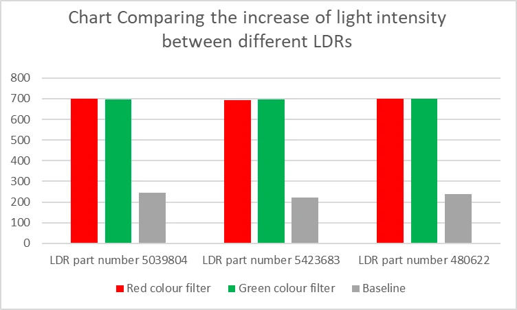
However, we feel that there could be improvements to be made in the process of detection, by placing a parabolic reflector behind the sample that is emitting light. This would allow the intensity of light directed at the LDR to increase and become more focussed as such grant a clear difference between the desired light and the scattered light of the surroundings. This is due to the fact that the fluorescent proteins that we are using are excited by visible light, and as such we had to find ways of differentiating between the desired and undesired light.
For the second method, we demonstrated that, at a nonzero angle of incidence, rays do not pass through the focal point as well as test the lasers with a diffraction grating. We found that while it was possible to achieve the intended effects, it would require careful precision that could not be done easily with human hands. Therefore, we think that for future improvements on this idea, it would be necessary to create pre-built 3D setups in order to achieve precise reflection and diffraction in order to achieve the desired results.
In reflecting on our work, we feel that we have proved the general principles of our designs, but that in our experiments we have found that there are serious changes that could be made to the designs of the detection mechanisms in order to improve them.
This can be seen in the fact that the readings when light is shone on the LDR are noticeable but not large, and as such we hope that in future, once we have access to fluorescent proteins (which we were not able to use currently due to delays in ordering) to test with, we will be able to improve on these results by using parabolic reflectors to increase the intensity of light emitted from the desired light source and lessening the amount of environmental light that can reach the LDR.
Moreover, it could be said that the diffraction and reflection detection method also demonstrates serious potential due to the control that is given to the user over which wavelengths of light are reflected into the LDR. However, this is undercut by the fact that this would involve incredibly precise measurements and calculations when setting up the parabolic mirrors and diffraction grating for each wavelength that you would want to detect. As such, when compared to the LDR-colour filter method, it seems that there would be greater setup costs involved with the diffraction and reflection detection method, but we are unsure if this would lead to better results.
We also believe that it may be viable to offer a combination of the two methods to allow for more control in which wavelengths are directed at the luminometer. As such it could remove possible interference or false positives from ambient light sources by directing only wavelengths within a desired range towards the luminometer and colour filters using the diffraction and reflection detection and result in clearer readings and results.